WCC-SF6
home
WCC-SF6
WCC-SF6
 WCC-SF6 system for laboratory/transfer standard preparation
 WCC-SF6 established systems for sampling compressed dry natural air and analyzing SF6 to prepare laboratory and transfer gas standards traceable to the WMO/GAW SF6 Reference Scale.
-
- Cleaning cylinders: aluminum cylinders are cleaned up with evacuating system, a turbo molecular pump and a heating apparatus of 60℃ more than 12 hours that is able to maintain the residual pressure inside the cylinder around 20 mTorr (Fig. 3(a)).
- Collecting air: Natural air sample is collected by an oil free air compressor through a dekabon tube from the top of 40 m height sampling tower. To remove moisture in the air sample, a chemical trap filled with granulated magnesium perchlorate is used (Fig. 1(b), (c), (d)).
-
Systems for preparation of compressed dry air in the cylinder 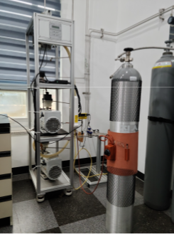
(a)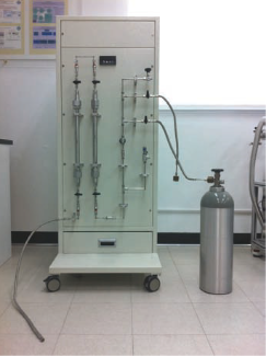
(b)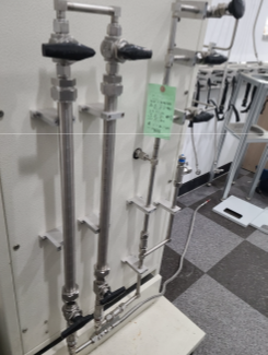
(c)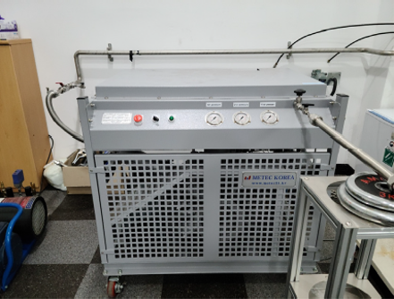
(d)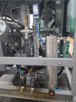
(e)Figure 3. Air filling system: (a) vacuum evacuating device and heating jacket, (b) dry air collecting system, (c) moisture trap, (d) air compressor, and (e) pressure gauge and pressure regulating valve
- WCC-SF6 Measurement system
- Method description: Preconcentrator + Back-flush
-
- When preparation of compressed air in the cylinders is ready, SF6 mole fraction of the samples are assigned by a gas chromatograph with electron capture detector (GC-μ ECD, Agilent 8890) with reference gases of the WMO/GAW SF6 mole fraction scale maintained by the CCL (in NOAA). (Fig. 2, 3)
- WCC-SF6 utilizes GC-?ECD analyzer (GC8890, Agilent) with and pre-concentrator for enhancing sensitivity. SF6 is concentrated to trap(carboxen-1000) at -80℃ of 4 min in pre-concentrator and separated in Activate Alumina F1 (1/8’’ 6ft, 12ft) column. The carrier gas used is high purity P-5 (Ar 95%, CH4 5%) and purge gas used is high purity He (>99.9999%).
- Gas flow: Gas cylinder → regulator → MFC (Mass Flow Controller) → Pre-concentration → sample injection valve (back-flush) → column → detector
-
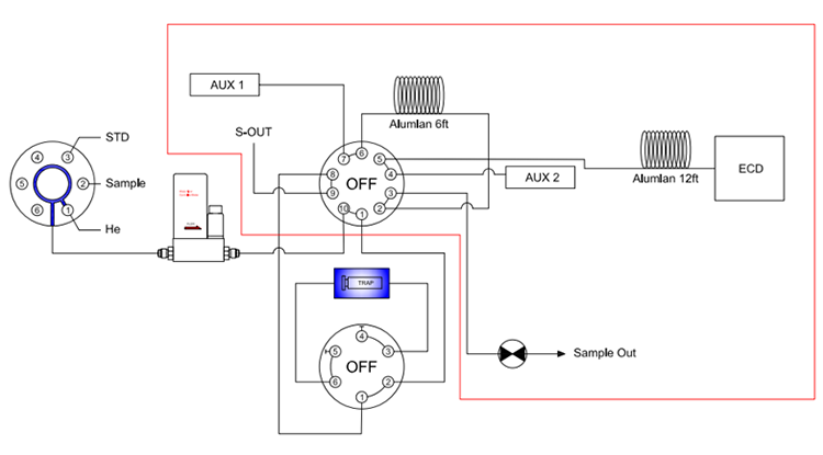
Figure 4. Valve configuration of preconcentrator and GC-ECD of WCC-SF6